A followup to Building a HackerSpace Badge, the four-part series on designing this thing.
I ordered twenty bare boards from JLCPCB on the seventh of July. They landed a week later, about three weeks earlier than I had planned for.
The first bare one is what got me. I made that. Up to that point it had only ever been a render on a screen, and here it was as an actual object with the Bit Haven logo printed on the front of it.
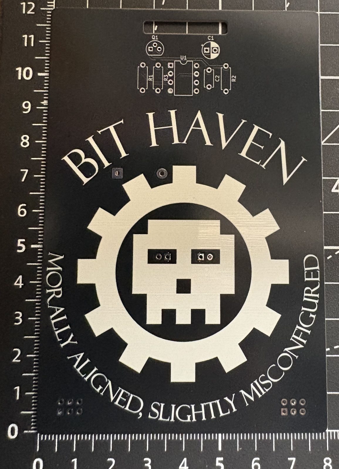
The bare board, straight out of the packet.
Building the first one
I followed my own guide, more or less. The chip went in first and I built the rest of the board out around it, with the bodge wire last.
I left the SAO headers off. By that point I had gone back and read the spec properly, and found that it expects 3.3V, while this badge runs at 4.5V off three AA cells. Anything anyone plugged into those ports would be getting more voltage than it asked for. There was no reason to solder on two connectors that were never going to be safe to use.
That one stings more than the transistor did. The transistor was an oversight. This was copying a feature off someone else’s board because it looked fun, without checking what it actually required.
I did not have the right battery holder either. Rather than wait on one, I wired up something else I had lying around and superglued it to the back of the board. It is not elegant. It does mean I can carry the thing around, which was the entire point.
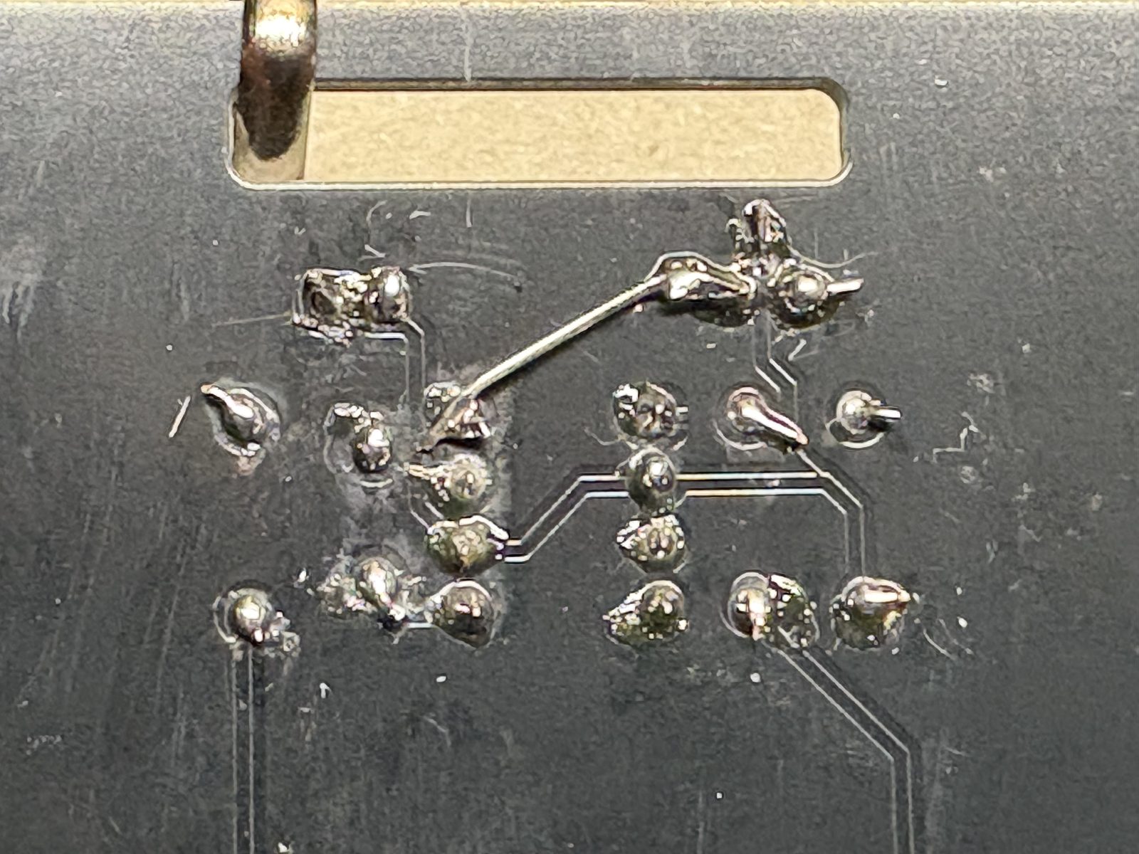
The bodge wire from Part 4, in the flesh. One short jumper from the transistor collector to pin 8.
Both eyes breathing, on a real board this time.
Once it was breathing, all I wanted to do was show it to people. This was a whole thing I designed, ordered and put together for the space, with my name on the back of it. I hope other people think it is as cool as I do, and I would rather it end up in their hands than sitting in a drawer.
What one of these costs
The twenty bare boards came to $66.05 shipped, which works out to about $3.30 a board. Most of that was not the fabrication. Boards this size are cheap to make, and the shipping on a small overseas order costs more than the fab does.
The parts are the smaller half. At twenty kits the through-hole components come to well under $1.50 a set, including the pair of SAO headers, which cost about twenty cents together. The one part that really moves the number is the battery holder, a three-cell AA holder that is both the tallest thing on the board and the most expensive single component in the kit.
So a complete kit, board and parts, lands under five dollars. Batteries on top, or builders bring their own.
Then they asked for five hundred
The people at the space liked it. Then the person who runs Bit Haven asked whether I could make it cheaper, because he wants around five hundred of them.
Not five hundred to sell. Five hundred to give away. The idea is to keep boards and parts on hand at the hackerspace so anyone who wanders in can sit down, solder one, and take it home. That is a far better life for this thing than twenty of them on a table one evening.
It also breaks my numbers. Under five dollars a kit is perfectly fine at twenty. At five hundred it is a two and a half thousand dollar order, and every single part on the board becomes worth arguing about.
How that would work is still loose. Nobody is kitting anything yet. My end is designing it and building test boards until the design is right, and the space would place the big order and buy the parts.
What I’d change on the next one
So the next version is a costing exercise as much as a design one.
The board needs to get smaller. Mine runs over 100mm on one side, and 100 by 100 is the line where the cheap fab tiers stop. Getting under that should bring the board cost down on its own, before I change a single component.
The battery holder is the other obvious target. Three AA cells is the tallest, priciest and most awkward part of the whole kit, and it is the thing people at the space commented on. I have not decided what replaces it yet.
A switch goes on. Right now the only way to turn the badge off is to pull a battery out, which means the cells drain whether anyone is looking at it or not. A switch is a few cents and it makes the thing last.
Four LEDs instead of two is a design choice rather than a cost one. I want to see what it looks like.
The SAO headers come off entirely. Two footprints and about twenty cents back, for a feature that was never going to work at this voltage.
The outline is still open. A gear echoes the logo, a circle is cleaner, and I honestly do not know yet whether a shaped edge cut costs more to fabricate than a plain rectangle. That is something I need to price before I decide rather than guess at. Whatever shape it lands on, it needs the lanyard cutout again, because a badge you cannot wear is just a circuit board.
Closing the loop
The badge exists and it works. That is not the same as being finished. The loop does not close until someone who is not me can build one. So I created the assembly guide, the bill of materials and the build photos, which are now up at Bit-Haven-Badge. The instructions are in solder order, low profile parts first and the battery holder last. The orientations are called out for the transistor, the LEDs and the electrolytic capacitor, because those are the three that will affect someone new. The Q1 to VCC bodge gets its own step and a warning not to skip it. There is a resistor color helper for anyone who has never read a band code, and a troubleshooting section for when the LEDs just sit there refusing to breathe.
I wrote it for someone who has never soldered, because that was always the point. A badge nobody else can build is a project, not a badge. With this complete I now need to get to the second iteration of the badge. To be continued.