Part 2 of 4 — Building a HackerSpace Badge · Previous: Finding the Circuit · Next: Designing the Badge in KiCad
I built the 555 flasher circuit on a breadboard, and getting there took a bit more work than I expected. I had to knock the rust off the 555’s pinout, and I was working off someone else’s schematic. Even with it in front of me I made mistakes on the breadboard and had to track them down before it finally ran.
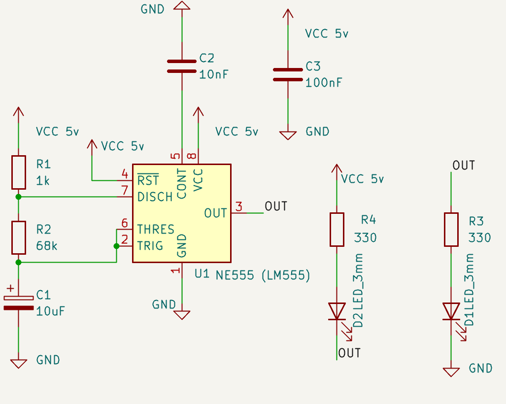
The 555 Dual LED Flasher. This is the one I ended up replacing.
Once it did, something still felt off. The two LEDs were going to be the eyes of the Bit Haven logo, and seeing them flash back and forth looked jarring. While the alternating LEDs worked exactly as intended, they just didn’t look right for a badge. It wasn’t the effect I was hoping for.

The Bit Haven logo. Those two empty eye sockets are where the LEDs go.
Another circuit I found while looking at 555 circuits was a fader, or breathing, circuit. I built it on the breadboard next to the flasher so I could see them side by side. It gave me trouble too. I missed the capacitor to ground on pin 5. It was in the schematic, I just did not put it on the board, and it would not run at all until I did. Once it was running, it just looked more aesthetically pleasing. And not like someone was trying to get your attention.
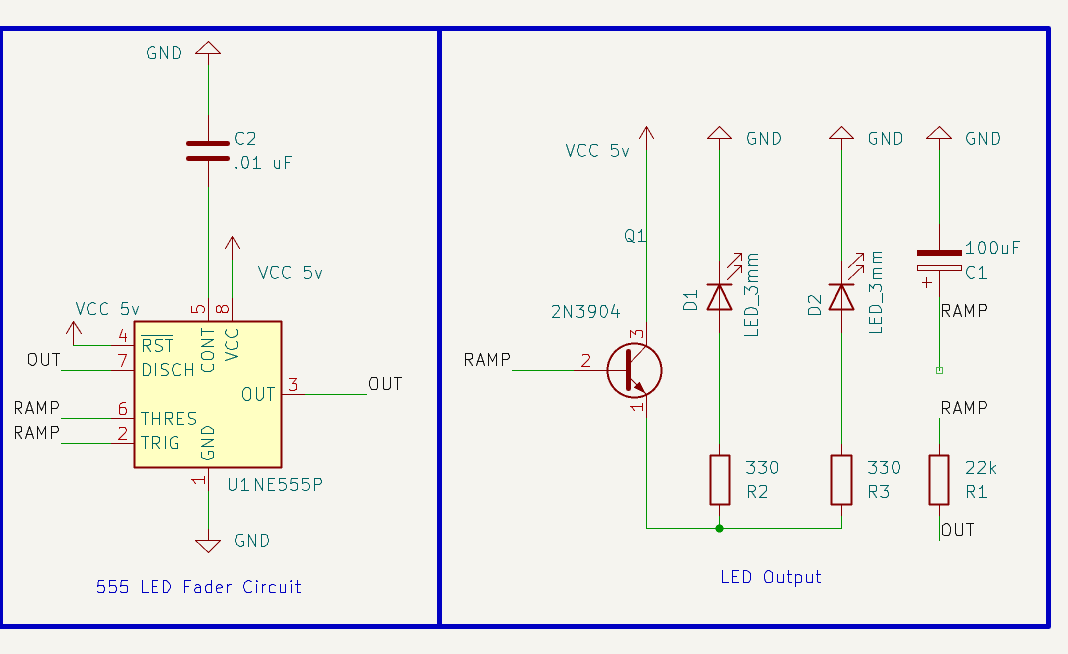
The 555 fader circuit on the left, and the output stage that drives the eyes on the right. This one is my own drawing.
The fader does not need much more than the flasher did. It adds a 2N3904 transistor, a 100uF capacitor, and a 22k resistor. The capacitor charges and discharges slowly through that resistor, and the transistor rides the slow ramp instead of switching hard on and off. The LEDs follow the ramp, so they fade instead of blink.
The wiring changed too. In the flasher the two LEDs sit on opposite sides of the 555 output, so they take turns. In the fader they share the same transistor, so both eyes fade together instead of trading off.
The difference was immediate. Instead of abruptly switching on and off, the two LEDs slowly faded in and out, so the badge looked like it was breathing instead of blinking. It felt less like a pair of blinking LEDs and more like the badge itself was looking back at you, and for barely any extra effort it just looked cooler.
The flasher on the left, the fader on the right, running side by side on the same breadboard.
That was the moment I knew the fader circuit was the right choice. With the electronics decided, the next challenge was turning a working breadboard prototype into a real PCB.